CRAYFORD FOCUSER IMPROVEMENT
by Christopher Krstanovic, Copyright NovaLab Observatory 2013

by Christopher Krstanovic, Copyright NovaLab Observatory 2013
Just like everyone else who uses automated Crayford focusers, I also experience the creep, i.e. the need to refocus after some number of adjustments due to the step loss. These focusers are usually run open loop, and the draw tube slips on the driving pin after a while. Running a long session with multiple filters (as I usually do) will require constant focus movements due to filter offsets, which is a problem if you are tracking something like an exoplanet – or if you are observing remotely as I do. I do not like to auto-focus too often, as this is very time consuming, and frankly too often it fails, no matter what software you use.
Click to zoom…
In attempt to cure this problem, I decided to try and add some abrasive to the flat of the drawtube, the idea being that it will not slip, or at least will slip much less. I use a Moonlite SCT focuser, and it worked so well, that I decided to share it with all of you.
It should be noted that the creep is cumulative, and appears to be related to the actual distance of travel, and not so much to direction reversals. My testing of the improved version shows that on successive 1000 full-step ± direction excursions (about ± 6.5mm each), I can detect only 40µm creep after 50 full cycles (that is 100 movements in total). This is far better than anything I observed on a stock product by a factor of 30 to100x. This translates into a 0.006% creep or 1 part in 16600 per distance travelled. BTW, this was a real creep, not the backlash, as I could observe it slowly building up over time.
A more typical operation would be using a ½ motor step, 1mm or lesser excursion (for filter offsets). In that mode I run out of patience in trying to observe any creep… but extrapolating on previous results, a 40µm creep would be observable after 660 mm of total travel, or that many 1mm adjustments. In an F4 system, with a theoretical depth of focus of about 50 microns, refocusing would be needed every 825mm of travel, and at F8 that is 3300mm of travel (basically forever). I am assuming the worst case of compensating for different thicknesses filters in the wheel, not miniscule adjustments due to the scope temperature drift. If this is all you do, it will outlast your focuser.
In short, now the filter offset in Maxim DL™ can be used for quite a long time (weeks), with no attention to focusing. I use it, and it works just fine.
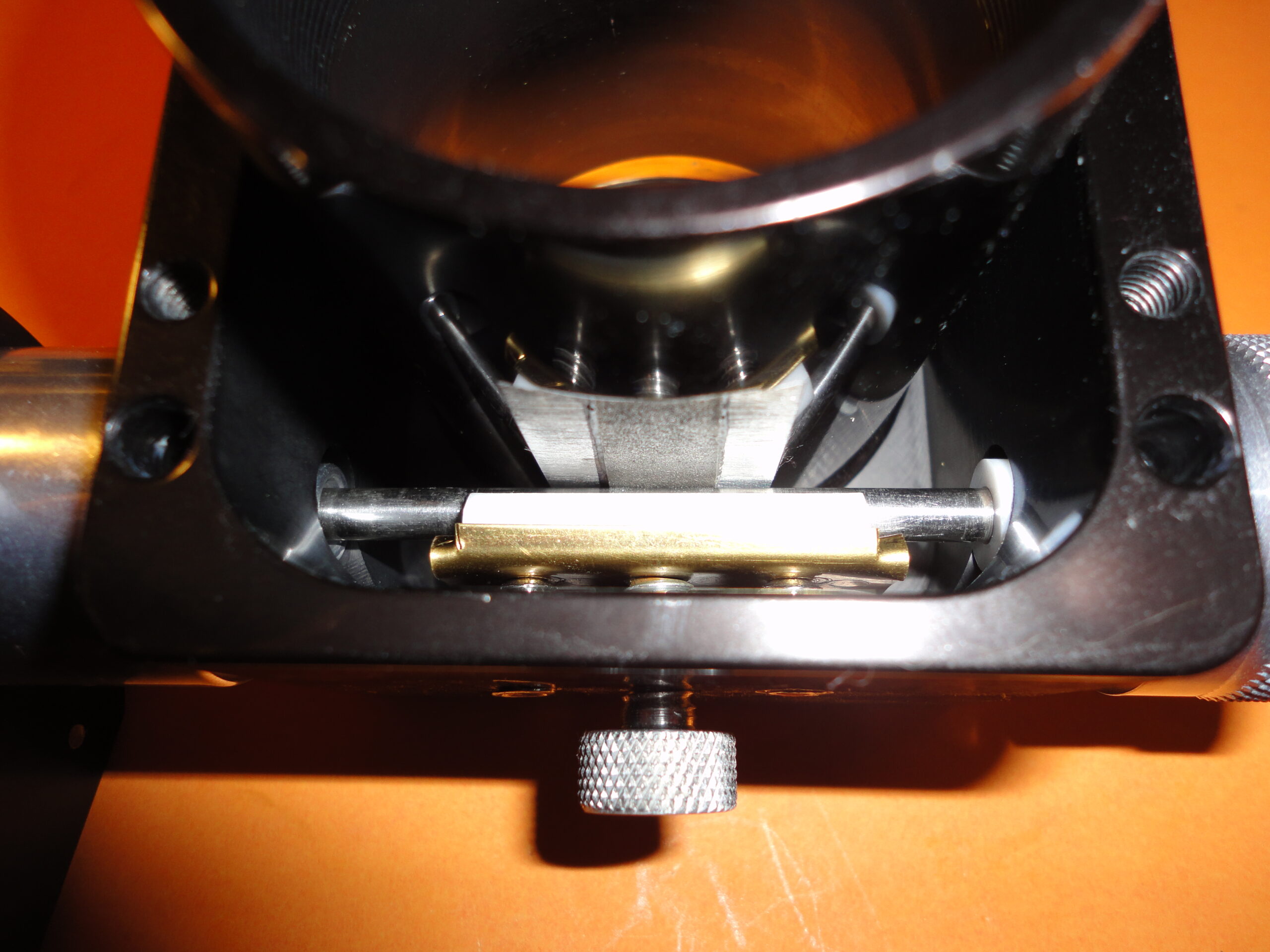
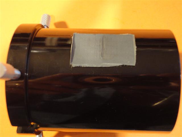
The final configuration consists of a piece of a thin metal nail file (CVS, couple of bucks, I bought a bunch to play with), with diamond abrasive embedded on both surfaces (estimated grit 300). This embedding bond is very strong, and the little bits do not fall off after the pin has rolled over them. The file was attached to the tube flat portion, for the Crayford pin to roll over.

In order for the focuser mechanics to be unchanged, the drawtube flat was milled down an additional 0.030”, to compensate for the file 0.025” and for the adhesive thickness. The adhesive used was JB Weld. The newly milled surface was lightly sanded to provide a better epoxy adhesion (or just rough mill). The file itself is two sided, and that bond will never fail.
It is very important to ensure that the file surface is completely flat relative to the tube. To ensure this, I had milled out a small Aluminum block of exactly the right size. This was used to press against the file surface in a vice, while the adhesive epoxy was curing (24 hours minimum). The other side of the tube had a soft, thick cloth to allow the tube to slide to a correct position in the vice, and yes, not to scratch it. Not a whole lot of force was used here.
Upon the installation into the focuser, the tube was manually rolled the whole length of travel, to ensure there are no “soft” spots. If one is found, the tension should be adjusted at that position, and then roll it again. In my case there were no soft spots.
The testing was done on the bench, with a 5 lbs. vertical load simulating the camera and the filter wheel. This is more than the Moonlite focuser is normally rated for. It should be noted that the focuser tension was considerably lighter than normally used, or the factory preset. The abrasive makes it pretty impossible for things to slip, so there is no need to stress the bearings or the abrasive. In the past, and in order to reduce the creep, I had tightened it so much, that the bearings cracked and needed replacement.
Although this is mostly relevant to the automated operation, I have also tested how smooth the focuser is for the manual operation, although this is hard to do with the motor assembly attached. In reality, I could not feel any real difference at all when using the 600 grit paper. Even the 300 grit (estimated) diamond file surface felt the same.
The 600 grit paper initially worked as good as the diamond file, but is structurally not strong and tears (see below). The diamond file seems to have suffered no ill effects after all the testing, or prolonged use during several months. All the pics above are after the testing.
My early tests were done using the 600 grit sand paper. Other grits, 1500 etc. work just as well to prevent the creep, but this approach is not a very long lasting solution. See below.
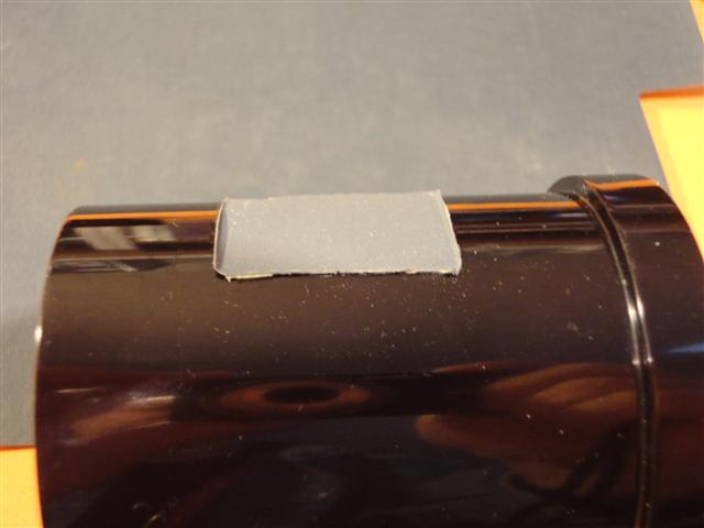
The paper delaminates and buckles (the superglue bond still remains intact)
Well, Moonlite motor gears do have it. I measure about 32 microns (or 10 half steps). Note that this is a unidirectional BL, i.e. only evident when moving against the load. When going with the load, none is observed. Nothing I can do about this, and it is not terrible for my operation on C11 at F7.5.
I would like to thank Ron Newman of Moonlite focusers for his help in this project, by sending ma a spare draw tube to modify. I have no material or other interest in Moonlite products.
This work was done in 2013.
Clear Skies,
Chris Krstanovic
NovaLab Observatory
Spencer, NC, USA